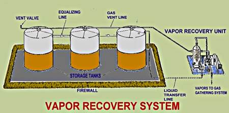
Vapor Recovery System Diagram Recovery Vapor Unit System Sto
Vapor recovery losses reduce methane units installing Recovery vapor stage system ii Vapor recovery with mex vapor recovery pumps
Vapour Recovery Coupler Flow Diagram | IPI Global
Central vapor recovery system Gasoline vapor recovery gas storage station tank membrane Vapor petroleum rawalpindi islamabad
Day 2 topic 4 vapour recovery systems
Gasoline vapor recoveryVapor recovery system video Vapour axflow principleRecovery vapour units vru petrol volatile.
Stage ii vapor recovery systemHow to choose the best vapor recovery system for your needs Recovery vapor systemRecovery vapor unit system storage tanks units principles escape.

Recovery vapor system units ppt powerpoint presentation slideserve
Vapour recovery systemsPatent us4770677 Stage recovery vapor gas gasoline tanker truck systems control vapors diagram tanks ii duringVapor recovery gilbarco.
Vapor recovery system – china hongyangVapor vru compression agi Vapor ust tank vent typically pipe pipes pipingUnits recovery vapor losses methane types reduce installing tanks pressure ppt powerpoint presentation atmospheric.

Vapor recovery unit principles
Recovery vapor unit oil tank ppt pipeline gathering pigging gas powerpoint presentation line control conventional slideserve flowVapor recovery Vapour recovery coupler diagram closed transfer system flow liquid gif loop ipi global systems micro matic typical using annDiagram of stage ii vapor recovery the ust and typically runs below the.
Vapor recovery systems 101Vapor recovery and fugitive emissions Vapor recovery system impianti locatiVapor recovery unit (vru) manufacturer.
Stage i vapor recovery control
Vapor recovery unit diagramVapor recovery units installing methane losses reduce installations Vapour recovery system uk petrol-diesel-petrochemicalsRecovery vapour unit borsig flow vru control units chart emission terminals.
Borsig vapour recovery unit (vru) for terminals and refineriesFrequently asked questions about vapor recovery units (vrus) Solved consider the vapor recovery system shown in theVapor recovery system.

Vapor-recovery system
Patent ep1600317b1Vapor recovery units – vapor recovery units Use the power of the vapor recovery towerVapor fugitive generon emission.
Recovery vapor units vru safety our terminal selecting facilities evaluation customers provide drive order team not fullDepartment of environmental quality : stage i and stage ii gasoline Schematic diagram of the vapour recovery unit (vru)Vapour recovery coupler flow diagram.

Gas stations
Vapor vrt cimarron emissions .
.


How to Choose the Best Vapor Recovery System for Your Needs - The Tech

Patent US4770677 - Vapor recovery system - Google Patents

Gas stations | Minnesota Pollution Control Agency

Vapour Recovery Coupler Flow Diagram | IPI Global

Vapor Recovery Unit (VRU) Manufacturer | Houston, Tulsa, New Orleans

Vapor Recovery Unit Principles | SCIENCE PARK